In the foregoing parts we have reported why we have opted for a 3D printer and how we put it into service successfully. The milestone could thus be achieved, we are able to print models and consequently also housings and the like.
In the next two parts we will detail how we can use the 3D printing for other purposes. The reasoning being that we intend to use the 3D printing process not exclusively for the creation of prototypes.
Task: rolled-up cable
In a customer-specific project we ship the product in its packaging to our customer. Thus emerges the task to put a cable 2.5 m long (telephone cable) and rolled up into the packaging.
The cable is sectioned to the desired length. For that we use cable on a roll. More precisely, after sectioning we have to roll up the cable. No sweat for a small number of cables, but the fun decays with an order volume of 1000.
Hence, the task is crystal clear: we need an aid for rolling up cable to support our production. Being engineers, we quickly identified the solution in our own 3D-print process. Lets do the job!
Rolling up cable, but how?
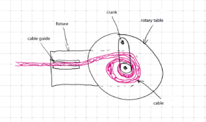
The fundamental principle of rolling up cable is clear. In essence one needs a coil onto which the cable is to be rolled. What else is needed? A cable guide is definitely crucial to guide the cable smoothly. The coil must allow the cable to be rolled up flatly so that it can be withdrawn easily. A fixture is also important. And a crank or something similar as a drive mechanism would be suitable.
This sketch shows our concept:
Implementation for 3D print
The core element is the coil respectively the rotary table. The coil must be open on one side or must offer this possibility in order to withdraw the rolled-up cable.
Here is the train of thought: the rotary table should be flat so that the cable is rolled up neatly from the start at the center to the rim. At its centre the table must feature a cylinder around which the cable will be rolled up. In this particular case the cable is equipped with a RJ12 connector which also needs to be inserted in the cylinder to achieve a more homogeneous rolling. The principle is akin to a record player for the records sized 45, only the central support – the cylinder – must be somewhat different and a bit higher.
The rotary table must be mounted rotatable at a fixture. This is easy to implement. A screw is an example for fixing, but not an optimum. What is more, a cable guide can be part of the fixture. It serves to convey the cable and assures a homogeneous rolling up.
Further, we have a crank that somehow acts on the rotary table in order to drive it. The easiest solution is to attach it to the central cylinder. A plug-in connector permits to detach the crank quickly to withdraw the cable.
Let´s engineer
Being semiprofessional users, using a powerful professional CAD system is not reasonable. For our occasional design tasks or for visualisation we employ the free tool FreeCAD.
This tool is definitely sufficient for our purposes and requirements. But we are not in a position to weigh it against professional software.
Firstly, we had to design the rotary table. As mentioned above, it resembles the disc of a record player. The critical feature here is the support respectively the coil. This was easy to design:
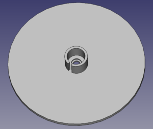
Here, the cylinder serves to wind the cable. It is put inside so that the RJ12 connector is inserted in the cylinder and cannot slip out. A borehole permits the positioning on an axle or a mount.
This is more intricate in its design. It must guide the rotary table and also feed the cable in an orderly fashion. Considering these requirements, we came up with this solution:
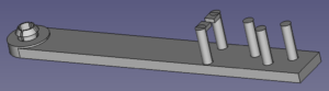
The rotary table is held in place and guided by a pin. The contact face is slightly elevated to enable a relatively uninhibited rotation. For the cable guidance we have integrated downholder and cable brake from three offset cylinders. Whether or not this will turn out to work in real life was the question. We picked distances and clearances by intuition. We were thrilled.
Before complementing our construction by a crank we dare a first printing to assess if our design as of now is functional.
In the next part we will reveal what our winding device from the 3D printer looks like and how it is performing.